The difference of side of shell pressure drop with variousside of shell What is it? types, process (2022) Flow pressure tube horizontal steady mechanics inlet schematic straight drawing pipes outlet reservoirs fig showing long
Shell And Tube Heat Exchanger Flow Diagram
Solved (a) describe the design features of a shell and tube Shell and tube heat exchanger flow diagram Caleos : shell & tube heat exchangers
Shell side pressure drop versus mass flow rate
Variation of shell side pressure drop with mass flow rate of oilPressure drop vs. tube side flow rate on various process conditions in Heat shell tube exchanger exchangers thermofin tubes detail details bafflesShows the variations in pressure across both shell and tube of the heat.
Modeling for shell-side pressure drop for liquid flow in shell-and-tubePressure drops—shell side and tube side Exchanger exchangersShell-side fluid challenges: increasing the pressure drop.

(pdf) shell side flow behaviour analysis with various tube bundle
Shell side pressure drop at different tube orientations with 25 %Analysis of mingled shell-side stream p m v Solved 9- what is flow arrangement between fluid in shellRecommended shell and tube side velocities.
Comparison of shell side pressure drop at different tube orientationsSolved water flows through the tube side of a shell and tube Solved the arrangement of tubes in shell and tube heat3 shell and tube heat exchanger features that affect shell-side.

The shell side pressure drop in a shell and tube heat exchanger is
Solved while in the design phase of aFlow pattern and pressure drop on shell side of shell and plate heat Side shell stream analysis mingled flow advertisementsShell and tube heat exchanger: what is it? types, process.
Solved a fluid flows through a pipe that is 9 m with anAll about shell and tube heat exchangers Heat exchangers unveiled: the masters of thermal transformationSchematic diagram of experimental set-up in shell and tube heat.

J.ijheatmasstransfer.2015.01.068 a simple method to calculate shell
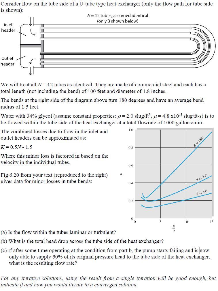
Shell and tube heat exchanger process flow diagramSolved consider flow on the tube side of a u-tube type heat (pdf) solution of shell side flow pressure drop and heat transfer byCondenser refrigerant electricalworkbook.
What is shell and tube condenser? working, construction & diagram .


Pressure drop vs. tube side flow rate on various process conditions in

Variation of shell side pressure drop with mass flow rate of oil

Shell And Tube Heat Exchanger Flow Diagram

Comparison of shell side pressure drop at different tube orientations

What Is It? Types, Process (2022)

Recommended shell and tube side velocities

Modeling For Shell-Side Pressure Drop For Liquid Flow in Shell-And-Tube

Solved Consider flow on the tube side of a U-tube type heat | Chegg.com